Hello everyone. Been a while and I have a new blog entry so that I don’t forget how to do this if I ever have to do it again.
I got my girlfriend a new Macbook Pro M1 for Hanukkah and she gave me her old one (It’s a Macbook Pro Mid 2012, or 14,1). I was going to update it to Mac OS 11, but found out that it didn’t support it, so I figured I would try to revive life to it by installing Ubuntu on it. This proved to be harder than I expected, but if you keep reading, I’ll tell you how I finally did it. (I’m actually writing this blog from the laptop running Ubuntu.)
So, the installation was pretty straight forward. I burned Ubuntu 20.04.2 on a DVD (From https://releases.ubuntu.com) and booted up the mac by inserting the DVD in the drive and holding down the “Option” key while booting up and I select the first EFI Partition to boot from by pressing the Up arrow after selecting it. It booted right into Ubuntu no problem.
I managed to install Ubuntu, and everything went smoothly. After installation, I noticed a weird error about MOK and EFI. I found out that Mac’s EFI wants a signed OS. To fix this, all I did was:
sudo su -
cd /boot/efi/EFI/ubuntu
cp grubx64.efi shimx64.efi
This will clear the black screen and error when booting.
Next, I ran sudo apt update & sudo apt upgrade -y to make sure I had all the updates to my laptop.
With the 20.04.2 update of Ubuntu, everything works out of the box with the Mid 2012 version of the Mac Book. If you run into any issues during the installation, leave a comment and I will try to help.
Hello everyone! It’s been a while since I updated my blog. I hope you all are staying safe and healthy.
I decided that I would write a blog about how I built my own video conferencing server during this whole outbreak with COVID and having to social distance and stay home.
My family is all over the country, and with travel and get togethers not being possible, I figured I would reach out and try to video conference with my family. However, we found that not all of us have iPhone or Androids, Laptops, and even comptuers running the same OS. Plus we all are Zoom’d out after work, so we didn’t want to use Zoom. So while taking a college class, I found out about Jitsi and decided I would try to create my own hosted video conference server. The thing I liked about Jitsi is that it has it’s own web client. So you can host and have meetings directly from the server using any web browser on any OS. It also has Apple Store and Google Play Store apps so you can connect that way, however, I had issues with the Google Play version of the App connecting to my server, but figured out the problem was with certificates and the Google version of the app not trusting my SSL certificates on my server. I will detail further on what I did to fix this issue.
This blog will detail how I did it using Ubuntu 20.04 as well as securing the server down so that not just anyone can use it and host video conferences.
First thing you need to do, is have a spare server that is capable of hosting the video conferencing software, as well as the users you want to have per conference. There are many discussions in forums about how to scale your server, but what I did for mine is 4 core CPU, 8GB of RAM, and 80GB of Storage. It has a 1GB NIC connected to my external network pool so that it is accessible directly on the Internet. I have had over 15 people at a time conferencing and it never went above 40% utilization of the CPU and never maxed out the network, and the experience was perfect. You can adjust as you see fit.
First, install Ubuntu 20.04.1 on the server. I use the Live Server ISO and configure the server and SSH and install my SSH Keys. I disable SSH password since I don’t use it and use keys only. I don’t install any Snaps since I don’t need that on this server. Once the OS installation is complete, reboot the server and login.
Next, I update all the repos and packages to make sure my system is fully updated:
$ sudo apt update && sudo apt upgrade -y
Next, I setup UFW to secure the server so that it is protected from the outside:
$ sudo ufw allow from xxx.xxx.xxx.xxx/24 to any port 22
$ sudo ufw enable
xxx.xxx.xxx.xxx is my internal network.
Next, I copy my SSL certificates and SSL keys to the server. I use the default locations in /etc/ssl/ to store my keys and certificates. I put the key in private/ and the certificates in certs/.
Now, before we can install Jitsi, I needed to make sure my hostname and /etc/hosts are configured for Jitsi to work correclty. I set the FQDN for my server using hostnamectl:
$ sudo hostnamectl set-hostname meet.domain.name
You can verify that it takes by running hostname at the prompt and it return the name you just set.
Next you have to modify the /etc/hosts file and put the FQDN of your server in place of the localhost entry.
Now we are ready to install Jitsi. Luckily, it has a repo that we can use, but we have to have the system trust it, so first we have to download the jitsi gpg key using wget:
Now we create the repo source list to download Jitsi:
$ sudo vi /etc/apt/source.list.d/jitsi-stable.list
i
deb https://download.jitsi.org stable/
Press the <esc> key to get the vi prompt and then type :wq to save and quite vi.
Now, run sudo apt update to refresh the repos on your system and then you are ready to install Jitsi by running:
$ sudo apt install jitsi-meet
You will be brought to a prompt where it asks for the server’s name, enter the FQDN of your server here. Next you will be asked about certificates. Select “I want to use my own certificates” and enter the path of your certificates and key.
Thats all it takes to install Jitsi. You now have a server that people can connect to and join and create video conferences. However, I don’t just want anyone to be able to create conference rooms on my server, so I locked it down by modifying some of the configuration files.
The first configuration file we need to modify is the /etc/prosody/conf.avail/meet.domain.name.cfg.lua file. This file will tell Jitsi to allow anonymous room creation, or password creation. Open the file in vi and find this line:
authentication = "anonymous"
and change it to:
authentication = "internal_plain"
Then, go all the way to the bottom of the file and add the following line:
Save the file and exit. These settings allow it so that only someone authenticated in Jitsi can create a room, but guests are allowed to join the room once it is created.
Next we need to modify the /etc/jitis/meet/meet.domain.name-config.js file. Edit and uncomment the following line:
// anonymousdomain: 'guest.meet.domain.name',
You uncomment it by removing the // from the front of the line. Save the file and quit vi.
The last file we have to modify is /etc/jitsi/jicofo/sip-communicator.properties file. Go all the way to the bottom of the file and add the following line:
org.jitsi.jicofo.auth.URL=XMPP:meet.domain.name
Now you are ready to add users to the system that you want to have the permissions to create rooms on the server. You will use the prosodyctl command to do this:
Last, restart all the Jitsi services so that everything you changed will take effect:
$ sudo systemctl restart prosody
You can now login to your meet server by opening a web browser to it, create a room, and you will be prompted to enter your Jitsi ID that you just created. It will be <username>@meet.domain.name and the password you set using the prosodyctl command.
Android Users and Jitsi
As I mentioned earlier, you can download the Jitsi app from the Apple Store and the Google Play Store. However, there is an issue with the Android version of Jitsi app where it only trusts Jitsi’s servers hosted on jitsi.org. To get around this with my friends and family, I shared with them my certificates for Jitsi in an email to them, and they installed them on their device. Once they did this they were able to connect to my Jitsi server using the Android app. IPhone and Web users do not have this issue.
Conclusion
I hope you liked this blog entry on installing your own video conferencing server. If you have any questions, or just want to leave a comment, leave it below.
Hey everyone! Been a while since I wrote a blog and I figured this would be a good one. So, because of the COVID-19, and everyone Social Distancing and schools being closed down. I decided that I was going to do a project. Me and my boys love retro gaming. We have used RetroPie in the past on Raspberry Pi’s and loved it, but we wanted to play some more modern games like from their Wii or Gamecube or PlayStation2, and those just can’t be done on the Raspberry Pi version of RetroPie.
I read a blog about running RetroPie on an Intel NUC, which I followed and for the most part, I got it working right. Some of my lessons learned will be in this HowTo. But after a while, we noticed that it just didn’t perform like it does on the PC or laptop with a decent graphics card. So after doing some research I found the Intel NUC gaming section, and purchased a Hades Canyon, which I feel will give us the performance we are looking for. Plus it will definitely give us the storage since PS2 Games are HUGE!
So, without further ado, here is how to get RetroPie working on your Hades Canyon (or regular NUC):
First thing you going to want to do is install Linux on the NUC. Burn the 18.04 Server ISO to a thumbdrive. I downloaded the Live Server version, but you can use the alternate. I recommend Server since you don’t need to install the full Desktop expirience, and I can use the space savings for more ROMS!!
Next, plug it in to the front USB port. Connect a keyboard up to the other USB port and connect the video and network. Luckily I have a mini switch next to my TV, so I just connected to that. Hades Canyon and NUC have WiFi, but I don’t use it.
Power on the NUC and it will automatically boot off of USB. You’ll get the GRUB menu and it will start the Live Installer for Ubuntu. I kept everything default, full disk, no LVM, no Encryption, DHCP on the Ethernet settings, and clicked install.
Setting up the user, I kept this simple and as close to the regular RetroPie settings:
User: Retro Pie
Server Name: retropie
Username: pi
Password: raspberry
I also told it to enable SSH and to download my public SSH keys from Launchpad.net and to allow remote password authentication.
After a few minutes, the install completed and I unplugged the USB thumbdrive and reboot the NUC. It restarted in Ubuntu 18.04.4.
I like to use the HWE kernel for my RetroPie since the newer kernel’s have new features and RetroPie might make use of them. So I do the following:
This will start the RetroPie installer. Accept the EULA and select Basic Installation. Select Yes to install all packages from Core and Main. They system will then start downloading and building RetroPie directly on the NUC
Note: This takes some time. Grab a beverage, some food. I’ll wait.
Once building and installation is complete, you can reboot the NUC from the menu. However, I have a few more customizations that I do.
I use an Xbox One Controller with my NUC, so I have to install the driver for it on Ubuntu. To do that, cursor down to Driver, and select the xboxdrv and install from source. It takes about 3 minutes to download and build the driver. When it completes, you are back at the Menu. Select Back from the bottom to go up a level, and do it again to get back to the main menu.
I also install Dolphin Emulator, and the Playstation2 Emulator, and they are found in the experimental section. They can be a trick to setup and work correctly. For me to get Dolphin to recognize the Xbox Controller correctly, I actually had to change my .bash_profile to enable cursor and window mode so that I could use the mouse on the screen so I could point and click the settings. Now that I have that done, I backed up the configuration from the old NUC, and just copied it to the new one with ease.
I also use Dolphin for Wii games, and I have a Dolphin Bar so that I can use my Wii controllers. This was a slight bear to setup. First, you need to create a couple udev rules:
sudo touch /etc/udev/rules.d/10-local.rules
sudo vi /etc/udev/rules.d/10-local.rules
Now, you can plug in the Dolphin Bar to a USB port and connect your controller. Make sure you are in Mode 4 for emulation mode on the Dolphin Bar, and then start Dolphin emulator by running it from /opt/retropie/emulators/dolphin/bin/dolphin-emu and select controllers. In the middle of the dialog, you will select “Emulate the Wii’s Bluetooth Adapter” and for the Wii Remotes, select Real Wii Remote. You won’t be able to configure them, but that is ok. Also check Continuous Scanning and save. Restart the NUC and now it will work. To verify, start Dolphin again, and make sure that the Wiimote is connected to the Dolphin Bar, when the game starts, the Wiimote will rumble letting you know its connected.
Also, Playstation and Playstation2 require BIOS’s to work.
After installing all the Emulators I want, I then go back to the main menu and select Configuration / tools.
I then configure Samba so that I can access my NUC’s ROM’s and am able to upload them using Samba. After it install Samba, select to Install Retropie Samba shares.
And now you are all done. This is where I reboot the device.
Now we are ready to setup the XBox One controller. First thing is to go to RetroPie Configuration in Emulation Station, and select Bluetooth. This will install the required Bluetooth libraries and binaries. Next, we need to SSH back into the box and make a setting change. XBox One controllers don’t use ERTM. Create a bluetooth.conf in /etc/modprobe.d/ and add the following line to the file:
options bluetooth disable\_ertm=Y
Reboot the NUC again. Now, go back in the RetroPie Configuration in Emulation Station, and select Bluetooth, set the Xbox Controller to be discoverable by turning it on, and holding the small button near the left bumper on top of the controller until the Xbox button flashes fast. Then in Emulation Station, select Search for controller. After a few moments it will be listed as Xbox Wireless Controller. Select it, and select the first option for connection and it will successfully connect. Back on the main screen in Emulation Station, press Enter or Start on another controller and select Configure Input. Select Yes and when it asks to press ‘A’ on a the controller, press A on the Xbox One Controller and you can configure it.
These next steps are just to make the system pretty. I don’t log the default Linux Boot up text scrolling on my TV, so I use Herb Fargus’s Boot themes using Plymouth, and set it to the RetroPie PacMan default setting:
And you’re done. May need to do some tweaks with the graphics to get good performance. I found that running in 4k tends to slow the games and audio down to unplayable, but found that if I play in 1080 mode, they work better. Before the game starts and it asks you to press a button to configure when running retro-arch, hit A button and select the emulator resolution from the list. Find one that works the best for you.
Hello everyone! Been a while since I posted a blog. This one was a doozy. I tried to find this information online and there was a ton to peruse through. Luckily, I was able to peice a few of them together to finally get it working the way I needed for my environment.
So, this is what I was doing. I needed to retire a KVM host, but it was running a couple of VM’s that I couldn’t migrate using virt-manger or with virsh migrate so I decided I would try to just move the qcow2 files and build them from new.
That did not work at all.
So, after researching some solutions, I finally have one that works, and I’m going to share it with you now.
NOTE: I shared my public ssh keys between the hosts so I don’t need to type passwords in when ssh’ing and scp’ing between the hosts.
First, power off the VM on the original host if it is running:
virsh stop <vm name>
Now, I had to chown the storage file since I don’t enable root on any of my systems and I needed to scp the file from one host to the new host:
sudo chown wililupy:wililupy server.qcow2
I could then scp it to the server where I keep my vm storage.
NOTE: The path for the storage of my VM’s is the same on both hosts, if it is different for you, you are going to have to make some modifications to the xml file that is part of the next step.
scp server.qcow2 host2:/data/vms
I then ssh into the new host and chown the file back to root:root.
Back on the first host machine, I execute:
virsh dumpxml server > ~/server.xml
I then change to root using sudo and copy the NVRAM file for my host since I use UEFI for my VM’s:
sudo -s
cd /var/lib/libvirt/qemu/nvram
cp server_VARS.fd ~wililupy
exit
cd ~
sudo chown wililupy:wililupy server_VARS.fd
I then scp’d the server_VARS.fd and the server.xml files to the new host:
scp server_VARS.fd server.xml host2:~
I then ssh’d to the new host and perform the following:
I was then able to start my VM’s on my new host and everything worked perfectly.
virsh start server
NOTE: My new host and old host had the same network and storage for the VM paths the same, which made this integration much easier. If yours are different, you will have to modify the xml file to match your new hosts information otherwise network will not work or the VM won’t find the storage correctly.
Leave me a comment if this helps or you need some pointers!
Ubuntu Core is a snap-only, lightweight version of Ubuntu. The kernel, the root file system, and the snap daemon are all packaged and operated as snaps compared to the traditional layout of a Linux distribution. Ubuntu Core is designed around IoT devices due to its lightweight, transactional updates and security. Deployment usually happens in the factory of the device and the software is “flashed” on to the storage medium.
MAAS, or Metal-As-A-Service, is a Canonical-based application that typically runs on a server or Top of Rack (ToR) switch that is used to manage and deploy various operating systems like Windows Ubuntu or Red Hat Linux and onto those bare metal servers. It is a way to treat bare metal servers as cloud services where you can manage it as easily as managing cloud instances.
With Ubuntu Core 18, cloud-init, which is the provisioning and configuration piece of Ubuntu, comes built-in. MAAS makes use of cloud-init to set up network access, initialize users, copy ssh keys to the device and to set up storage and partitions.
This document will explain how to set up MAAS to be able to deploy Ubuntu Core to devices, which devices are compatible with MAAS so that it can be used to deploy and what customizations have to be done to the Ubuntu Core image to have seamless integration with MAAS and the target devices.
MAAS Setup
Installing MAAS is fairly easy. There are two methods of deployment: you can either install it from the main repo in Ubuntu Server after the server has been deployed, you can install MAAS during the initial installation of Ubuntu Server, or you can install it via snap packages on any Linux distribution capable of running snaps. This document will cover installing MAAS from the MAAS/next repository that is the beta next release of MAAS (2.5) in Ubuntu 18.04.2. More information on other installations can be found here.
Deploy Ubuntu Server
Download the latest version of Ubuntu Server 18.04.2 by clicking here.
Burn the media to a USB or DVD and install Ubuntu Server by following the Installation Guide located here.
Once Ubuntu Server is running, do an update to make sure you have the latest versions of the software: sudo apt update && sudo apt upgrade -y
Once this completes, you need to add the MAAS/next ppa to your apt.repos: sudo apt-add-repository -yu ppa:maas/next
Now, install MAAS on the server: sudo apt install maas -y
Once MAAS finishes installing, you need to configure an admin user account. Use the following command to do this: sudo maas createadmin --username=admin Enter a password and email address for the admin user and now you are ready to login to the web UI. However, we have one small step left to do since the next following steps will require command line use.
Now, we need to save the API key to login to the MAAS command line. This is how we will upload the Ubuntu Core image to MAAS so that it can be deployed on devices. Use the following command to save the key: sudo maas apikey --username=admin > ~/apikey This will save the API key to your home directory as apikey. This will be used later when we actually upload the Ubuntu Core image to the server.
Configuring MAAS
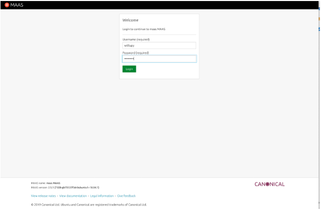
Now, we need to finish setting up MAAS. Login to the web UI by opening a browser window to: http://maas.server.address:5240/MAAS
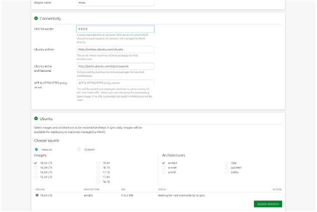
After you login, you are presented with a screen asking for DNS forwarders. Here you can add your own internal DNS servers, or use the public ones. You can also leave it blank, but I recommend at least entering 8.8.8.8. You also need to have at least one image downloaded and installed, By default MAAS downloads the X86_64 version of Ubuntu Server 18.04. You can add others if you want, but this should suffice for now.
Scroll all the way to the bottom and click Continue.
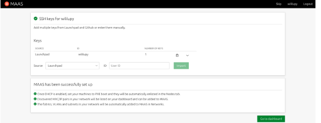
On the next screen, import any other SSH keys you want MAAS to be able to provision to servers/devices and then click import and then click Go to dashboard to go to the Main MAAS UI.
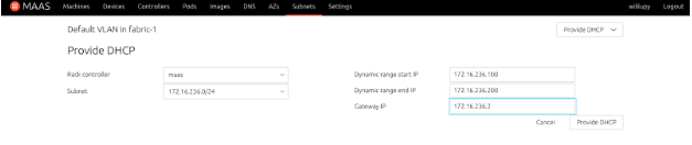
From the main dashboard, click the Subnets tab. We need to setup DHCP on the network that will be managing the servers and devices.
Click on the VLAN for the subnet you want to manage DHCP for. Click the ‘untagged’ label.
From the Action button, select Provide DHCP and configure the address pool and the gateway for the subnet and then click Provide DHCP button.
MAAS is configured now to manage and deploy images that are connected to the subnet that you just configured. You can click on the Machines tab and you are ready to start enlisting, commissioning, and deploying Nodes.
OPTIONAL: Setup MAAS as a Router using UFW
This step is optional. If your network that is managing the subnet has a router or a policy that routes traffic to the internet or other networks, this step can be bypassed. If you are testing on a Canonical OrangeBox this can be skipped since the mini switch in the box has routing capabilities built in. However, if you are running this in a VM environment or just testing locally on a subnet you created in your home lab, this will help get your clients you deploy with MAAS to get to the internet and work properly. I used UFW since it is built in to Ubuntu and fairly easy to configure, just a lot of rules for the various ports that MAAS uses to do its “magic.”
Below is a list of ports that MAAS uses:
Port
Use
7911/TCP
MAAS
22/TCP
SSH
53/TCP and UDP
DNS
3128/TCP
iSCSI
8000/TCP
Squid
5240/TCP and UDP
MAAS
5247/TCP and UDP
MAAS
5248/TCP
MAAS
5249/TCP
MAAS
5250/TCP
MAAS
5251/TCP
MAAS
5252/TCP
MAAS
5253/TCP
MAAS
67/UDP
DHCP
68/UDP
DHCP
69/UDP
TFTP
123/UDP
NTP
5353/UDP
Multicast DNS
5787/UDP
MAAS
Now, for the procedure to enable NAT and forwarding in MAAS using UFW. NOTE: It is much easier to work with the firewall as root. You can switch to root using the following command: sudo -s
Setup the forwarding policy for UFW by modifying the /etc/ufw/default and change the following: DEFAULT_FORWARD_POLICY=”ACCEPT”
Uncomment net/ipv4/ip_forward=1 from /etc/ufw/sysctl.conf to allow ipv4 forwarding. You can also uncomment the ipv6 if you need it.
Next, modify the /etc/ufw/before.rules to create the NAT table and the source network and interface by adding the following BEFORE the filter rules:
# NAT table rules
*nat
:POSTROUTING ACCEPT [0:0]

# Forward traffic through the external interface on host
-A POSTROUTING -s 172.16.236.0/24 -o ens33 -j MASQUERADE

# Don’t delete the ‘COMMIT’ line or this nat table rules
# won’t be applied
COMMIT
Now we are ready to create the firewall rules to allow connectivity to MAAS and the various services. Below are the commands to do this:
You will get a list of the firewall rules. You can connect a device to your internal network managed by MAAS, and try to ping Google.com or 8.8.8.8 and verify that you get a return echo. If that is all working properly, then you have successfully setup MAAS to act as a router for clients on the managed network.
Ubuntu Core Image Setup
Ubuntu Core 18 can deploy from MAAS out of the box. However, there is currently a bug in console-conf where if MAAS manages the device and configures the network, console-conf will fail on the network setup and go into a loop where you cannot configure the device. You can still manage to ssh and login using your keys that are installed to the device via MAAS managed keys, but you cannot login locally on the console of the device because it does not know it is fully configured.
There are also some limitations of what you can configure for the device through MAAS. For example, you cannot change the filesystem and partition layout since the image is basically just dd’d to the device, so after installation and first boot, Ubuntu Core resizes the partition to fit the device, and installs the correct partitions to be able to boot the device up properly. The only parts that Ubuntu Core uses from cloud-init is the network configuration and it creates a user named Ubuntu on the device, and then copies the stored SSH keys for the MAAS user deploying the device onto the device for remote login/administration.
To get around the previous mentioned bug, before we install the image into MAAS, we have to add a file so that it doesn’t run console-conf after first boot. The following procedure will go into this in detail.
Download Ubuntu Core 18 and upload it to the MAAS Server
Download the latest version of Ubuntu Core 18 from here.
SCP the image to the MAAS server: scp ubuntu-core-18-amd64.img.xz maas.server.address:~
SSH to the MAAS server: ssh maas.server.address
Login to the MAAS CLI using the APIkey you created previously: maas login admin http://localhost:5240/MAAS `cat ~/apikey`
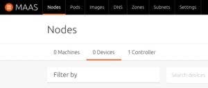
Verify that the image uploaded by going to the Images tab in MAAS UI and at the bottom you will see Custom Images, and the image will be there:
You are now ready to deploy Ubuntu Core to a device managed by MAAS.
Implementation
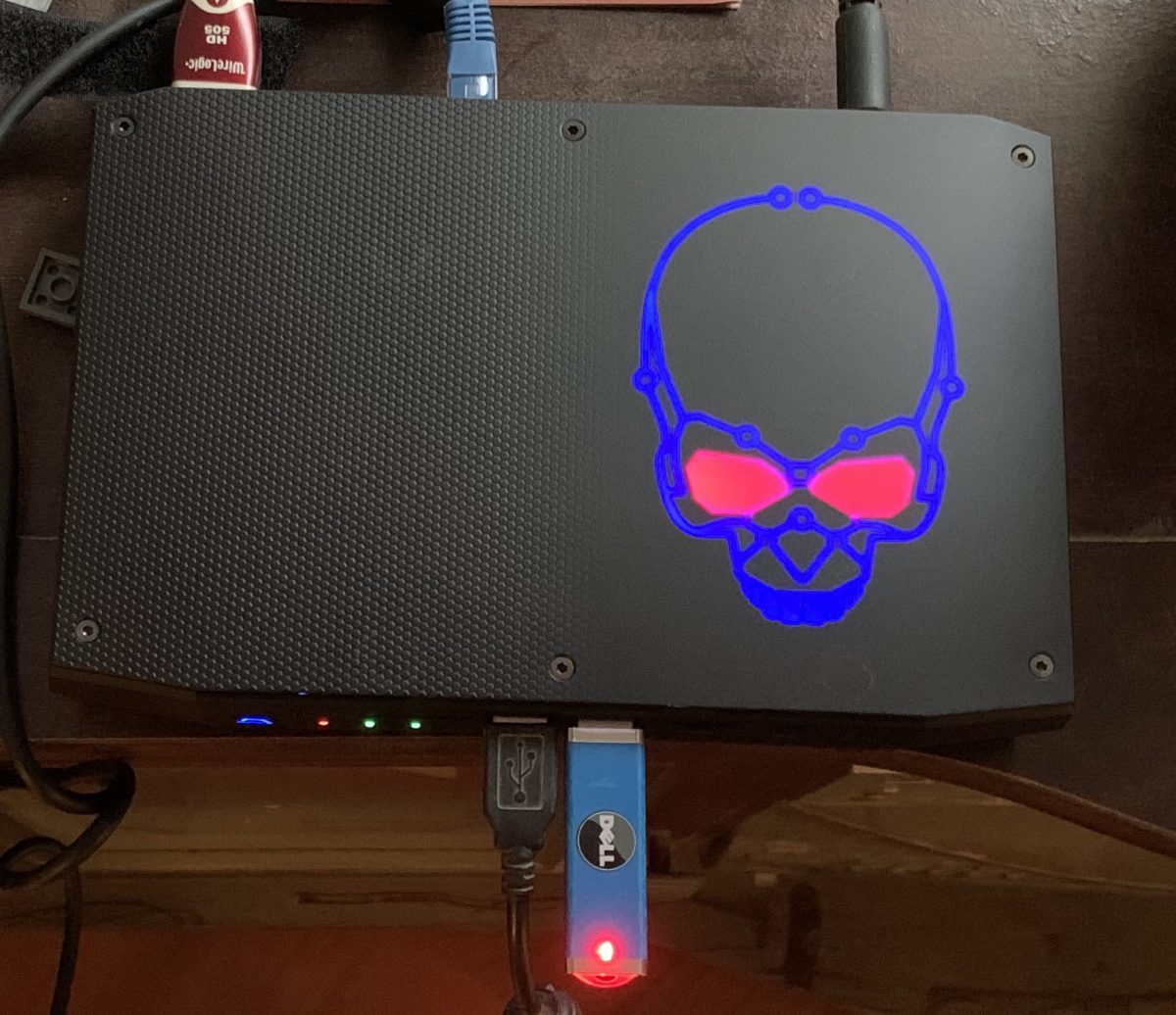
So now we are ready to deploy Ubuntu Core 18 on to a device. First, make sure that your device is connected to the network, there is no OS installed on the device, and that it is setup to PXE boot. Make sure that you connect the power to a managed UPS outlet, or if it has a remote poweron/off ability, that you have the credentials or settings and that they are compatible with MAAS. For this demo, I used an Intel NUC, which uses Intel AMT for the power management. I configured it on the NUC in the BIOS and then entered in those settings when I got to that step.
MAAS has three phases when it acquires new devices. First, the device needs to be powered up and MAAS will automatically detect a new device on the network when it asks for a DHCP address. MAAS will boot up an ephemeral image and probe the device for network connectivity, and power management, and if it can, power off the device, and then add it to the MAAS database. This is called “Enlistment.”
Once this step is completed, from the MAAS UI, the operator can then “Commission” the device. This boots up an ephemeral image on the device and probes all the hardware, gets more detailed information, and can perform tests on the device and also upgrade firmware if required. Once this step is completed, the device is ready to be Provisioned, or deployed.
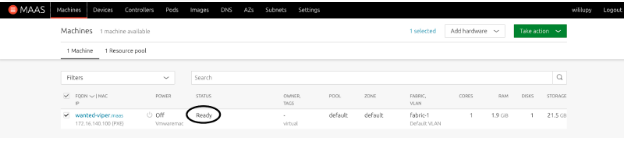
To provision a device, once it is in the Ready state, you can select it from the Machine tab in MAAS, and from the Action button, you select Deploy.
Below will be the steps to enlist, commission and deploy Ubuntu Core 18.
Enlistment
Connect the device to the network being managed by MAAS. Make sure it is fully configured to use remote power up and down.
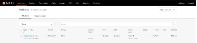
Power on the device. You can either connect to the console of the device or install headless and watch MAAS. Once the device is enlisted, it will show up in the Machine tab.
Doing this sometimes will cause the system to not know the power type to use. You may have to configure the power for the device for remote power on. For Intel NUC’s, they use AMT, but some make use of IPMI. You can also select Managed PDU’s as well. If it is a VM, you can use KVM or VMware. VirtualBox is not supported.
When enlistment is finished, you will get the following in the Machine tab in MAAS:
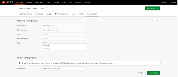
If enlistment couldn’t detect the power type, you will have to manually update it. Select the node.
Click on Configuration
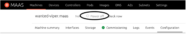
From the Power type pull-down, select the power type that the device uses and enter all the applicable information. If it is entered correctly, you will get the following indication on the machine:
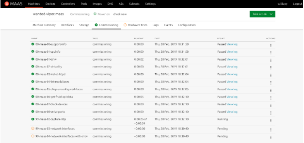
Commissioning
When the device is in a “New” status, it needs to be commissioned before it can be deployed. From the Machine tab screen, perform the following:
Select the device from the Machine tab.
From the Take action button, select Commission.
You can watch the hardware test and the commission scripts run from the respective tabs in the Machine view in the MAAS UI:
Once all the hardware tests and commission scripts have passed, the machine will be powered off and put in the Ready state.
Deployment
The device is now ready to have Ubuntu Core 18 installed. Follow this procedure for deploying Ubuntu Core.
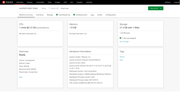
From the Machine tab in the Web UI, select the device you want to deploy Ubuntu Core to.
From the Machine view of the device, you will see various tabs. These tabs let you customize the installation of the device.
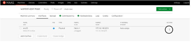
Click on the Interfaces tab. This tab lets you configure the network address of the device. To customize it, click the Action icon highlighted in the following picture and select Edit physical.
The Storage tab does not function with Ubuntu Core, so any selection you make will not apply to Ubuntu Core. This is due to how Ubuntu Core is installed on the device. Since it is just dd’d on to the device, it will auto partition on first boot so that Ubuntu Core will work as designed with the writable partition and the boot/EFI partitions.
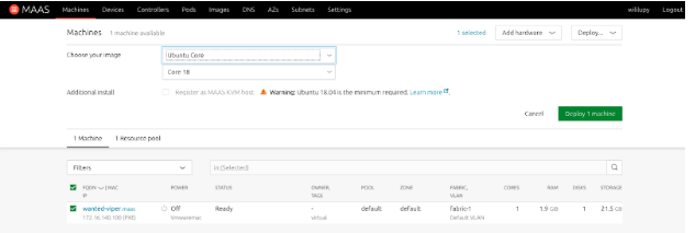
From the green Take action button, select Deploy
From the Choose your image pull down, select Ubuntu Core.
Make sure that Core 18 is the image that it will install.
Select Deploy Machine
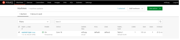
Once deployment is finished, the device will remain powered on and have Core 18 in the status. You can now SSH to the device with the user ubuntu.
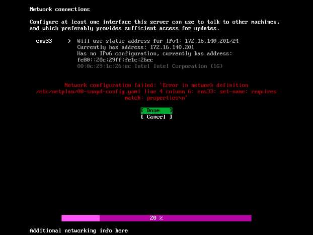
NOTE: Even though the device is saying that it is deployed, if you look at the console of the device, it will be at the first boot state. This is a bug in Console-conf where even though the device is configured, console-conf is not aware of this. If you try to configure the device, it will fail at the network setup with the following error: If you select Done, you get back on this screen. If you select Cancel, you end up on the main configuration screen and you can’t move past this. To work around this, we need to let console-conf know that the device is already configured.
SSH to the device. ssh ubuntu@device.name
A file needs to be placed in /var/lib/console-conf called complete. sudo touch /var/lib/console-conf/complete
Reboot the device and when it comes back online, you will be presented the normal login screen on the console. However you cannot login via the console due to security of Ubuntu Core 18.
Conclusion
With this document, you can now deploy Ubuntu Core 18 to devices that are managed by MAAS. I hope that this has been helpful and informative.
So for the last few weeks, I have been dealing with a DoS attack happening against me. After spending a couple days with Comcast Network Engineers we finally figured out that my mail server was being attacked. Once we disabled the NIC on the server, Internet service would start up immediately and everything appeared to be working properly. Looking at the auth logs, I noticed that port 80 and port 22 were getting bombarded by the DoS attacks.
Since the Comcast gateway has a poor firewall, I looked in to getting an upgraded PAN to meet my demand, but unfortunatly, that was going to set me back about $4k, and I looked at Untangle, but ran into configuration issues with the Comcast Gateway and my static IP’s.
So, until I save my pennies to get the upgraded PAN I had to use ufw to block my attacks.
UFW, or Uncomplicated Firewall, is the default Firewall for Ubuntu. Since my mail server is running Ubuntu, I decided to use this. And it is fairly easy to setup and use.
First thing I noticed when being attacked is that specific Chinese IP addresses were attacking the server on port 22 and port 80, which are the SSH port and the unencrypted default web server port. So these were going to be the first ones that I setup, however, one thing to note is that when you enabled ufw, it blocks all traffic, which is a good thing really, however, when you rely on email for your job, blocking it all is not good. so I needed to find out what external ports I needed to have open to the public so that it would still work, and which ones I could have just available internally so that I can still work on the servers if I need to.
First thing I did was look at what ports my server was sharing outside. I did this with the netstat command:
netstat -an | more
This command outputs all the interfaces and ports that the server is listening and communicating on. This also tells you who is connected to what service if they have an open session, so this command is pretty important if you are wanting to get into security.
To make it easy, I needed imap, pop, smtp, ssh, http, https, and ldap.
I also needed to know what can be internal only and what needs to be exposed to the public so that my email server can still get email.
Here is what I came up with:
Ports
Visibility
22 (SSH)
Internal
25 (SMTP)
public
443 (HTTPS)
public
993 IMAP
public
465 (SMTPS)
public
587 (SMTP Submission)
public
80 (HTTP)
Internal
110 (POP3)
Internal
143 IMAP
Internal
389 (LDAP)
Internal
995 (IMAPS)
Public
So, now that I have the required information, I can create the rules. They are as simple as doing the following command:
sudo ufw allow from x.x.x.x/24 to any port 22
This rule allowed only my internal IPv4 network to connect to the server. I did this for all internal addresses. I also added the specific email external IP address with a /32 to specify only the server could talk to itself on the internal ports. Might have been overkill, but better safe than sorry. For my public rules I did the following command:
sudo ufw allow from any to any port 443
This will also create IPv6 rules as well.
If you accidently create a rule and it isn’t working properly, you can remove the rule by first looking up its number:
sudo ufw status numbered
and then:
sudo ufw delete [rule #]
Once everything is done, enable the firewall so that the rules will be applied:
sudo ufw enable
If you every need to stop the firewall, you can disable it by sudo ufw disable and it will go back to being unsecured.
I still had to reboot the server after creating the rules and enabling the firewall since sessions were still open but after the reboot, I haven’t had any more issues and email still works. You can look at the syslog to see all the blocks, which is somewhat fullfilling.
If you have any questions, or if you have any comments, please leave them below!
Thanks!
Been a while since I wrote here. Figured I would write up a howto to setting up a Unreal Tournament 2004 server. I really love this game. It brings back tons of memories, playing this when I was in the Navy with my friends on the sub.
My boys have some break time off from school, and they played a little bit back in the day, so I decided to spin up a server so that we could play. I looked for a way to do this online, and couldn’t find anything so I figured I would write something up, so here you go.
So, the good thing is that because the game is pretty old now, over 13 years old now, it doesn’t really require a lot of CPU or memory or storage. I deployed a KVM with 2 cores and 4GB of RAM and 20GB storage server running Ubuntu 16.04.3, and got all the updates installed. I then spent the next few hours searching for the ut2004 dedicated server package. Never could find it. Luckily, I had a backup copy, which I have uploaded to this server so you can download it here. You’ll also need the patch, which you can download here.
I created a directory for the game in /usr/local/games/UT2004 and extracted the .zip here:
Once that was complete, I then untarred the patch and had to manually install it, since it creates a directory called UT2004-Patch so I had to actually go into each directory and move the files into their respective directories in the UT2004 directory. Once that was complete, you now have a system capable of running Unreal Tournament 2004 server. However, I needed to do a couple more things.
Next, you need to install libstdc++5 package. This is required so that Unreal can run. Run the following command to install libstdc++5:
sudo apt install libstdc++5
One, I decided to start the web admin. In the /usr/local/games/UT2004/System/UT2004.ini. Find the UWeb.Webserver section and modify it:
You can change the ListenPort to what ever you want, you just need to change bEnabled=False to True to enable it.
Next, I decided that I wanted this to run as a service using SystemD instead of just running in the background with me logged in to the server. Below is my UT2004-Server.service file:
[Unit]
Description=Unreal 2004 Dedicated Server
After=network.target

[Service]
Type=simple
User=ut2004
WorkingDirectory=/usr/local/games/UT2004/System
ExecStart=/usr/local/games/UT2004/System/ucc-bin-linux-amd64 server CTF-BridgeOfFate?game=XGame.xCTFGame?AdminName=admin?AdminPassword=XXXXXXXX ini=UT2004.ini log=server.log -nohomedir
Restart=on-abort
Just change the ?AdminPassword= to what you want I then copied the file into /lib/systemd/system and chmod 644 and chown root:root the ut2004-server.service file and now I can control the service with systemctl:
systemctl start ut2004-server.service and I can get status with systemctl status ut2004-server.service
One last thing I did as well is I included my cdkey from my game since I was getting errors about a missing cdkey, however, I have tested it, and it is not required. The game will still run, you just can’t advertise your server on the Internet and host Internet games without it, which means your stats also won’t work. You used to be able to download a CD-Key from Epic, but that service is no longer working. I emailed them about this on December 2, 2017 with no reply as to date.
So I spend a lot of time deploying switches in my lab for my job. I also really like Canonical’s tools for managing infrastructure and bare metal servers called MAAS, or Metal-As-A-Service. It can deploy servers better than really any other solution I have used in the past, including Red Hat’s Satellite, Microsoft’s Windows Deployment Services (WDS) and Solaris’s Jumpstart server. The thing I particularly like is that it is OS agnostic. Meaning even though it is a Canonical product, it is not restricted to just Ubuntu. I can setup MAAS to deploy any, Operating system to my bare metal, as long as I have an image for it. So I can deploy Red Hat and Windows as well.
So I was thinking, how hard would it be to make MAAS deploy ONIE images on Bare Metal Whitebox switches? The answer is, really easy. Since MAAS is using a Web backend based on Apache2, it has the default directory structure for Apache2. So in /var/www/html I can put my ONIE images for my switches in that location. Also, becuase MAAS is the DNS and DHCP server for my managed devices and servers, it is a no brainer on using this to deploy whitebox switches.
Typically, when deploying ONIE images on to a Whitebox switch, Network Administrators have a couple options. They can either use a USB thumb drive with the ONIE image burnt on it and restore it via the ONIE Rescue option in the ONIE GRUB Boot menu and then typing install_url file:///path/to/onie-installerand then it install, but that is only efficient if you are deploying maybe 1-5 switches. As a Network Engineer, if I have to leave my seat to reset and update my switches, that is unsat. And if I’m carrying my “serial leash” over my shoulder, that is a walk of shame…
The other option is to use the Network Boot option, which is the default way of deploying a NOS onto a Whitebox switch. This is the automatic option, but it does depend on a couple of things:
The ONIE image is named specifically for the device, of example, a Celestica Redstone XP switch has the default ONIE installer image name of onie-installer-x86_64-cel_rxp_sxp-r0 and if it can’t find that specific image, it starts decrementing down to onie-installer-x86_64-cel_rxp_sxp to onie-installer-x86_64 until it can find an image. Then it checksums that image to make sure that it will work on the device based on the machine.conf.
That the DHCP server is also the web server that is hosting the image. Now this is subjective, because you can have the default-url set in your DHCP server to point to the location of the ONIE images.
As you can see, there a pros and cons to both deployments. Now to get why I like MAAS to do this.
MAAS is a DHCP, DNS, and Web server all in one pretty package. I can plug my whitebox switch’s management port into the network that is managed by MAAS and set it up as a Device in MAAS so that I know what the IP address will be.
I can put the ONIE image directly on MAAS in the /var/www/html directory and ONIE will automagically pick it up and install
One thing to note, is that I cannot directly manage the switch from MAAS. Meaning that I cannot use MAAS to configure the NIC ports, and I cannot use MAAS to setup local users on the device or use MAAS to deploy an OS from the list of installed images on my MAAS server. Now there are plans that this functionality will come in the future, but it will not be based on ONIE images, and instead be PXE installed and managed by MAAS and specific images that are switch supported. This is outside of the scope of this blog entry, but as soon as they do become available, you can bet I will write a blog entry on how to do that.
So, to get MAAS to deploy your whitebox switches, these are the steps:
Copy your ONIE installer images to /var/www/html on the MAAS server.
Under the Node tab, there is a Devices option at the top of the Web page, click that and enter the MAC address of the switch, as well as the name you want to give the device and the IP address if you don’t want to have a dynamic address assigned to the switch. I highly recommend that you set a static so that you don’t have to guess what the address is of your switch to manage it in the future.
Power on (ie, plug in) the switch
On the serial console of the switch, watch as the device comes online and starts ONIE, it will by default go into ONIE Install OS and start the install process
When complete, the switch will reboot and the NOS will start up
SSH into the switch via the static IP address that MAAS assigned to it
You’re done.
So now you can use MAAS to not only manage your servers, but it can deploy your NOS on to your Whitebox switches. You can also use this procedure for upgrading the NOS using ONIE on your Whitebox switches.
DISCLAIMER: This is not supported by Canonical. If you try this and it doesn’t work, you cannot contact Canonical for support. They do not support ONIE or the NOS’s that are deployed on the switches that are not running Ubuntu. This article is just showing that you can use MAAS to do this if you so wish to be able to have this and not have to have a separate server to deploy ONIE images from and have a one stop shop for your infrastructure deployments. While this should not impact MAAS functionality or deploying other services through MAAS, you are making changes to the directory structure that is not supported by Canonical.
I wrote this article because I have had many Network Engineers and Admins ask if they could use MAAS to deploy ONIE images, which yes, you can, but Canonical will not support it since it is not a Canonical supported deployment method.
If you have any questions, or just want to say “Great article” leave a comment!
Been a little while since I posted a blog entry. I’m at the OpenStack summit in Boston this week, and I am doing a demo of Mellanox’s SwitchDev running on Ubuntu 17.04, Zesty Zapus.
By default, we at Ubuntu enable SwitchDev in the Kernel. Also, because Zesty is running the latest stable kernel (4.10) and has the latest updated SystemD, SwitchDev runs out of the box. No need to configure or apply any patches, it just works.
I am demoing in the Mellanox booth at OpenStack Summit Ubuntu, running on a Mellanox SN2100 switch, with SwitchDev enabled. This demo also shows that because it is running Standard Ubuntu Server, you can install other Canonical technologies on it, such as Metal-as-a-Service (MAAS) and Juju. The Demo is running MAAS on the switch, and it is managing 10 servers running in an Ubuntu Orange Box and with Juju, we are deploying OpenStack on to the servers in the Orange Box.
Hello everyone! I have been rebuilding my network and servers due to a major outage that I had with my ISP, which we are still meddling with. However, during the outage, I had to rebuild my servers. So I lost a lot of my build machines. Luckily, I still had copies running on my Mac running VMware Fusion. However, I don’t run on there so my machines just sit powered down, but if I need to bring them up for anything, I can.
Well, I have a build machine that was running out there before I brought it into my KVM environment, but it was out of hard drive space and under utilized. This blog post is going to show how I moved the hard drive to my kvm server and then how I resized it and got it up and running.
First thing I did was scp the vmdk file from my Mac to my KVM server:
After that finished, I was able to get info on it:
qemu-img info precise-build.qcow2
image: precise-build.qcow2
file format: qcow2
virtual size: 80G (85899345920 bytes)
disk size: 73G
cluster_size: 65536
Format specific information:
    compat: 1.1
    lazy refcounts: false
    refcount bits: 16
    corrupt: false
I wanted to grow it to 200GB in size:
qemu-img resize precise-build.qcow2 +120G
I then got info on it to verify that it grew:
qemu-image info precise-build.qcow2
image: precise-build.qcow2
file format: qcow2
virtual size: 200G (214748364800 bytes)
disk size: 75G
cluster_size: 65536
Format specific information:
    compat: 1.1
    lazy refcounts: false
    refcount bits: 16
    corrupt: false
I was now ready to build the VM, which I used Virtual-Manager to build. I told it to use an existing disk, and then set it up to use more memory and processors then previously so I could get better performance out of it. I then told it to boot from a CD image of Parted-Magic so I could grow the file system. Luckily, this server only had two partitions, the root partition at the swap partition. However, the swap was on an extended partition and at the end of the disk. So I had to delete it and the extended partition so I could used parted to extend the file system. I extended it to the end minus 6GB, and then created at extended partition at the end and added a swap partition back and then saved it and rebooted. The machine rebooted, ran fsck and started up normally.
I was then able to delete the vmdk file from my server to reclaim the 73GB of space it was using:
rm /data/VMS/precise-build.vmdk
Thats it. I hope this guide helps you migrating VM’s and growing their file systems from VMware or even Virtual Box to KVM.