Hey everyone! Been a while since I wrote a blog and I figured this would be a good one. So, because of the COVID-19, and everyone Social Distancing and schools being closed down. I decided that I was going to do a project. Me and my boys love retro gaming. We have used RetroPie in the past on Raspberry Pi’s and loved it, but we wanted to play some more modern games like from their Wii or Gamecube or PlayStation2, and those just can’t be done on the Raspberry Pi version of RetroPie.
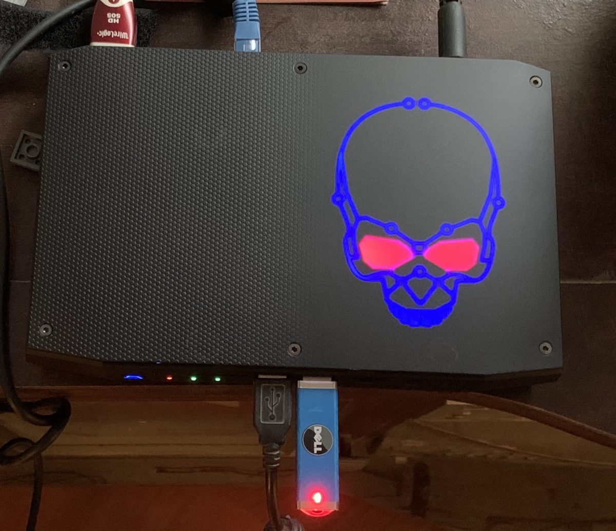
I read a blog about running RetroPie on an Intel NUC, which I followed and for the most part, I got it working right. Some of my lessons learned will be in this HowTo. But after a while, we noticed that it just didn’t perform like it does on the PC or laptop with a decent graphics card. So after doing some research I found the Intel NUC gaming section, and purchased a Hades Canyon, which I feel will give us the performance we are looking for. Plus it will definitely give us the storage since PS2 Games are HUGE!
So, without further ado, here is how to get RetroPie working on your Hades Canyon (or regular NUC):
First thing you going to want to do is install Linux on the NUC. Burn the 18.04 Server ISO to a thumbdrive. I downloaded the Live Server version, but you can use the alternate. I recommend Server since you don’t need to install the full Desktop expirience, and I can use the space savings for more ROMS!!
Next, plug it in to the front USB port. Connect a keyboard up to the other USB port and connect the video and network. Luckily I have a mini switch next to my TV, so I just connected to that. Hades Canyon and NUC have WiFi, but I don’t use it.
Power on the NUC and it will automatically boot off of USB. You’ll get the GRUB menu and it will start the Live Installer for Ubuntu. I kept everything default, full disk, no LVM, no Encryption, DHCP on the Ethernet settings, and clicked install.
Setting up the user, I kept this simple and as close to the regular RetroPie settings:
- User: Retro Pie
- Server Name: retropie
- Username: pi
- Password: raspberry
I also told it to enable SSH and to download my public SSH keys from Launchpad.net and to allow remote password authentication.
After a few minutes, the install completed and I unplugged the USB thumbdrive and reboot the NUC. It restarted in Ubuntu 18.04.4.
I like to use the HWE kernel for my RetroPie since the newer kernel’s have new features and RetroPie might make use of them. So I do the following:
sudo apt update
sudo apt upgrade
sudo apt install --install-recommends linux-generic-hwe-18.04
And then you reboot the NUC again. Once it comes back up you are ready to do RetroPie installation. This is what I did:
SSH into the NUC
Set it so the the pi user can execute sudo without a password (makes scripting much easier)
sudo sed -i -e '$a\pi ALL=(ALL) NOPASSWD:ALL' /etc/sudoers
Type the pi password and you’re all set. You won’t have to type that password again if you use sudo.
Now to add the universe repo and all of the RetroPie dependancies:
sudo apt-add-repository universe
sudo apt update -y
sudo apt upgrade -y
sudo apt install xorg openbox pulseaudio alsa-utils menu \ libglib2.0-bin python-xdg at-spi2-core dbus-x11 git \
dialog unzip xmlstarlet --no-install-recommends -y
Now we need to create an OpenBox autorun script to start terminal and start Emulation Station
mkdir -p ~/.config/openbox
echo 'gnome-terminal --full-screen --hide-menubar -- \ emulationstation' >> ~/.config/openbox/autostart
Next, create the .xsession file:
echo 'exec openbox-session' >> ~/.xsession
Now we need to make it so X11 starts on reboots:
echo 'if [[ -z $DISPLAY ]] && [[ $(tty) = /dev/tty1 ]]; then' >> ~/.bash_profile
sed -i '$ a\startx -- -nocursor >/dev/null 2>&1' ~/.bash_profile
sed -i '$ a\fi' ~/.bash_profile
Next, we make it so the that pi user automatically logs in and that way Emulation Station will be what you see on the screen:
sudo mkdir /etc/systemd/system/getty@tty1.service.d
sudo sh -c 'echo [Service] >> /etc/systemd/system/getty@tty1.servcie.d/override.conf'
sudo sed -i '$ a\ExecStart=' /etc/systemd/system/getty@tty1.service.d/override.conf
sudo sed -i '$ a\ExecStart= /sbin/agetty --skip-login --noissue --autologin pi %I $TERM' /etc/systemd/system/getty@tty1.servcie.d/override.conf
sudo sed -i '$ a\Type=idle' /etc/systemd/system/getty@tty1.servcie.d/override.conf
Now we are ready to download RetroPie from the Git Repo and run the installation scripts:
git clone --depth=1 https://github.com/RetroPie/RetroPie-Setup.git
sudo RetroPie-Setup/retropie_setup.sh
This will start the RetroPie installer. Accept the EULA and select Basic Installation. Select Yes to install all packages from Core and Main. They system will then start downloading and building RetroPie directly on the NUC
Note: This takes some time. Grab a beverage, some food. I’ll wait.
Once building and installation is complete, you can reboot the NUC from the menu. However, I have a few more customizations that I do.
I use an Xbox One Controller with my NUC, so I have to install the driver for it on Ubuntu. To do that, cursor down to Driver, and select the xboxdrv and install from source. It takes about 3 minutes to download and build the driver. When it completes, you are back at the Menu. Select Back from the bottom to go up a level, and do it again to get back to the main menu.
I also install Dolphin Emulator, and the Playstation2 Emulator, and they are found in the experimental section. They can be a trick to setup and work correctly. For me to get Dolphin to recognize the Xbox Controller correctly, I actually had to change my .bash_profile to enable cursor and window mode so that I could use the mouse on the screen so I could point and click the settings. Now that I have that done, I backed up the configuration from the old NUC, and just copied it to the new one with ease.
I also use Dolphin for Wii games, and I have a Dolphin Bar so that I can use my Wii controllers. This was a slight bear to setup. First, you need to create a couple udev rules:
sudo touch /etc/udev/rules.d/10-local.rules
sudo vi /etc/udev/rules.d/10-local.rules
Now paste the following into your rules file:
#GameCube Controller Adapter
SUBSYSTEM=="usb", ENV{DEVTYPE}=="usb_device", ATTRS{idVendor}=="057e", ATTRS{idProduct}=="0337", TAG+="uaccess"

#Wiimotes or DolphinBar
SUBSYSTEM=="hidraw*", ATTRS{idVendor}=="057e", ATTRS{idProduct}=="0306", TAG+="uaccess"
SUBSYSTEM=="hidraw*", ATTRS{idVendor}=="057e", ATTRS{idProduct}=="0330", TAG+="uaccess"
Now, you can plug in the Dolphin Bar to a USB port and connect your controller. Make sure you are in Mode 4 for emulation mode on the Dolphin Bar, and then start Dolphin emulator by running it from /opt/retropie/emulators/dolphin/bin/dolphin-emu and select controllers. In the middle of the dialog, you will select “Emulate the Wii’s Bluetooth Adapter” and for the Wii Remotes, select Real Wii Remote. You won’t be able to configure them, but that is ok. Also check Continuous Scanning and save. Restart the NUC and now it will work. To verify, start Dolphin again, and make sure that the Wiimote is connected to the Dolphin Bar, when the game starts, the Wiimote will rumble letting you know its connected.
Also, Playstation and Playstation2 require BIOS’s to work.
After installing all the Emulators I want, I then go back to the main menu and select Configuration / tools.
I then configure Samba so that I can access my NUC’s ROM’s and am able to upload them using Samba. After it install Samba, select to Install Retropie Samba shares.
And now you are all done. This is where I reboot the device.
Now we are ready to setup the XBox One controller. First thing is to go to RetroPie Configuration in Emulation Station, and select Bluetooth. This will install the required Bluetooth libraries and binaries. Next, we need to SSH back into the box and make a setting change. XBox One controllers don’t use ERTM. Create a bluetooth.conf in /etc/modprobe.d/ and add the following line to the file:
options bluetooth disable\_ertm=Y
Reboot the NUC again. Now, go back in the RetroPie Configuration in Emulation Station, and select Bluetooth, set the Xbox Controller to be discoverable by turning it on, and holding the small button near the left bumper on top of the controller until the Xbox button flashes fast. Then in Emulation Station, select Search for controller. After a few moments it will be listed as Xbox Wireless Controller. Select it, and select the first option for connection and it will successfully connect. Back on the main screen in Emulation Station, press Enter or Start on another controller and select Configure Input. Select Yes and when it asks to press ‘A’ on a the controller, press A on the Xbox One Controller and you can configure it.
These next steps are just to make the system pretty. I don’t log the default Linux Boot up text scrolling on my TV, so I use Herb Fargus’s Boot themes using Plymouth, and set it to the RetroPie PacMan default setting:
sudo apt update
sudo apt install plymouth plymouth-themes plymouth-x11 -y
git clone --depth=1 https://github.com.com/HerbFargus/plymouth-themes.git tempthemes
sudo cp -r ~/tempthemes/. /usr/share/plymouth/themes/
rm -rf tempthemes
sudo update-alternatives --install /usr/share/plymouth/themes/default.plymouth default.plymouth /usr/share/plymouth/themes/retorpie-pacman/retropie-pacman.plymouth 10
sudo update-alternatives --set default.plymouth /usr/share/plymouth/themes/retropie-pacman/retropie-pacman.plymouth
sudo update-initramfs -u
sudo cp /etc/default/grub /etc/default/grub.backup
sudo sed -i -e 's/GRUB_TIMEOUT=10/GRUB_TIMEOUT=2/g' /etc/default/grub
sudo sed -i -e 's/GRUB_CMDLINE_LINUX=""/GRUB_CMDLINE_LINUX="quiet splash"/g' /etc/default/grub
sudo update-grub
This piece hides the last login information before starting OpenBox:
sudo sed -i -e 's/session optional pam_lastlog.so/#session  optional pam_lastlog.so/g'/etc/pam.d/login
sudo sed -i -e 's/session optional pam_motd.so motd=\/run\/motd.dynamic/#session optional pam_motd.so motd=\/run\/motd.dynamic/g' /etc/pam.d/login
sudo sed -i -e 's/session optional pam_motd.so noupdate/#session optional pam_motd.so noupdate/g' /etc/pam.d/login
sudo sed -i -e 's/session optional pam_mail.so standard/#session optional pam_mail.so standard/g' /etc/pam.d/login
And to hide the terminal in Emulation Station:
sed -i '1 i\dbus-launch gsettings set org.gnome.Terminal.Legacy.Profile:/org/gnome/terminal/legacy/profiles:/:b1dcc9dd-5262-4d8d-a863-c897e6d979b9/ use-theme-colors false' ~/.bash_profile
sed -i '1 i\dbus-launch gsettings set org.gnome.Terminal.Legacy.Profile:/org/gnome/terminal/legacy/profiles:/:b1dcc9dd-5262-4d8d-a863-c897e6d979b9/ use-theme-transparency false' ~/.bash_profile
sed -i '1 i\dbus-launch gsettings set org.gnome.Terminal.Legacy.Profile:/org/gnome/terminal/legacy/profiles:/:b1dcc9dd-5262-4d8d-a863-c897e6d979b9/ default-show-menubar false' ~/.bash_profile
sed -i "1 i\dbus-launch gsettings set org.gnome.Terminal.Legacy.Profile:/org/gnome/terminal/legacy/profiles:/:b1dcc9dd-5262-4d8d-a863-c897e6d979b9/ foreground-color '#FFFFFF'" ~/.bash_profile
sed -i "1 i\dbus-launch gsettings set org.gnome.Terminal.Legacy.Profile:/org/gnome/terminal/legacy/profiles:/:b1dcc9dd-5262-4d8d-a863-c897e6d979b9/ background-color '#000000'" ~/.bash_profile
sed -i "1 i\dbus-launch gsettings set org.gnome.Terminal.Legacy.Profile:/org/gnome/terminal/legacy/profiles:/:b1dcc9dd-5262-4d8d-a863-c897e6d979b9/ cursor-blink-mode 'off'" ~/.bash_profile
sed -i "1 i\dbus-launch gsettings set org.gnome.Terminal.Legacy.Profile:/org/gnome/terminal/legacy/profiles:/:b1dcc9dd-5262-4d8d-a863-c897e6d979b9/ scrollbar-policy 'never'" ~/.bash_profile
sed -i '1 i\dbus-launch gsettings set org.gnome.Terminal.Legacy.Profile:/org/gnome/terminal/legacy/profiles:/:b1dcc9dd-5262-4d8d-a863-c897e6d979b9/ audible-bell false' ~/.bash_profile
cp /etc/xdg/openbox/rc.xml ~/.config/openbox/rc.xml
cp ~/.config/openbox/rc.xml ~/.config/openbox/rc.xmlbackup
sed -i '//a ' ~/.config/openbox/rc.xml
sed -i '//a true ' ~/.config/openbox/rc.xml
sed -i '//a no ' ~/.config/openbox/rc.xml
sed -i '//a below ' ~/.config/openbox/rc.xml
sed -i '//a no ' ~/.config/openbox/rc.xml
sed -i '//a yes ' ~/.config/openbox/rc.xml
sed -i '//a ' ~/.config/openbox/rc.xml
And lastly, if you want to suppress cloud-init, lets just remove it since we don’t need it:
sudo apt purge cloud-init -y
sudo rm -rf /etc/cloud/
sudo rm -rf /var/lib/cloud/
And you’re done. May need to do some tweaks with the graphics to get good performance. I found that running in 4k tends to slow the games and audio down to unplayable, but found that if I play in 1080 mode, they work better. Before the game starts and it asks you to press a button to configure when running retro-arch, hit A button and select the emulator resolution from the list. Find one that works the best for you.
Happy Retro Gaming!